PCOMP Lab 1
A brief introduction to Physical Computing

Basic DC Setup
Let us embark on the first steps of physical computing. First, a bit of setup:
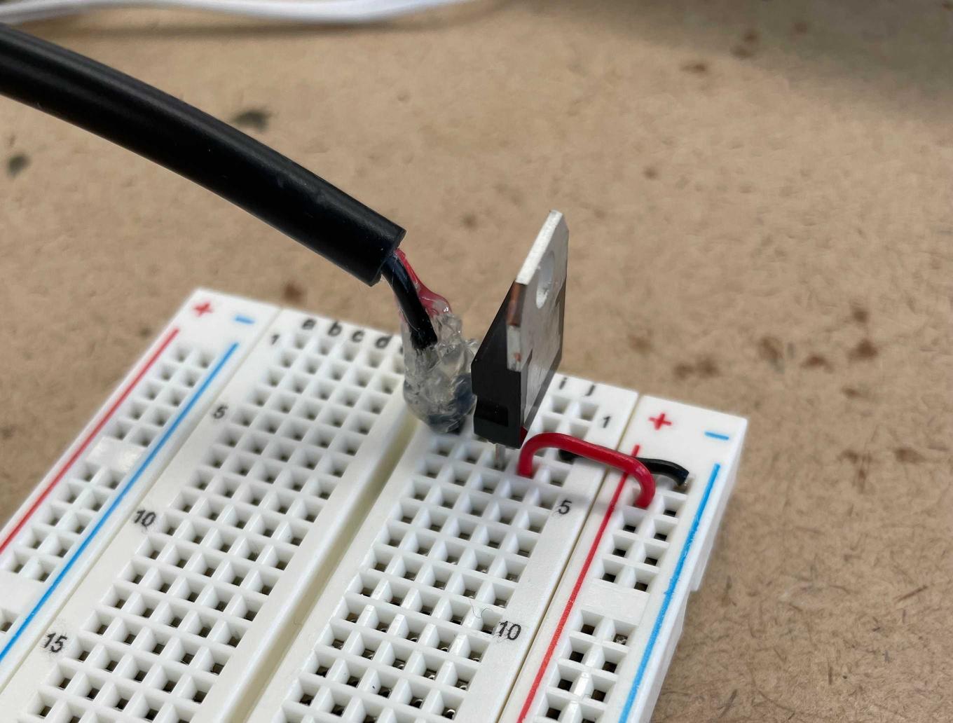
Above is a basic DC input setup with regulator. I soldered the jack to some headpins and hot-glued them for security.
Above, lighting a single LED.
When setting up this DC input, it should be noted that the voltage regulator can only be used when also using a wall plug providing 9-12 volts. If the source provides less than 9v, you won’t get much power on the other side of the regulator (a mistake that I made and was confused by for far too long).
LEDs
Up next, a few basic things with LEDs. An LED lighting up, LEDs in parallel and series, and hooked up to a little switch.
Adding up voltage:
- The switch is is 3V closed, 0V open
- Resistor is 1v, each LED is approx 2V
When a third LED is added in series, the LEDs light up but only barely. Not enough power is being supplied to the LEDs, as each LED needs approximately 2V to work.
Switches
Here, we learn to use a potentiometer, switches in series and parallel, and how to attach a motor.
A Custom Switch
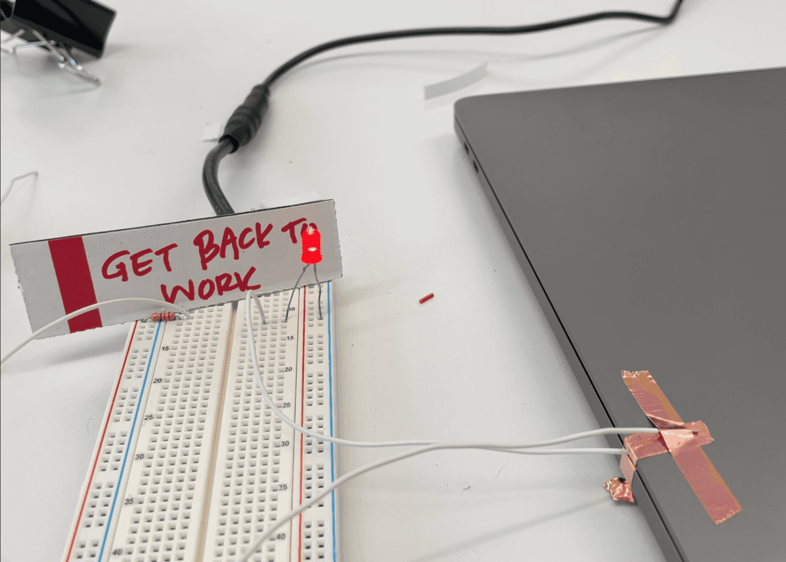
Lastly, let me leave you with a little custom switch. This may be the most expensive switch I’ve ever used.
Tagged:

